Another project completed as part of my MSEE degree, this time for the course in Power Electronics. Our professor, Dr. Greg Mowry of the University of St. Thomas, allowed each of us to choose a published power electronics paper and then verify its results, including simulating any topologies. It was interesting to see what my classmates came up with during presentations on the last day. One pair actually found enough errors in their selected paper to disprove it!
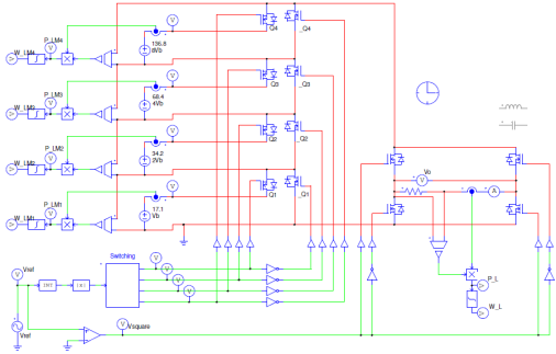
I found a paper which presented a novel topology for a single-phase multilevel inverter that is scalable for photo-voltaic (PV) arrays. The authors were a bit opaque regarding how they controlled the thing for grid connection, so I couldn’t verify everything. But I did have a good time simulating the topology in PSIM.
As part of my work towards my MSEE, I completed a simulation project of a 4-wheeled mecanum vehicle. I became intrigued with this kind of motion after seeing our First Robotics Competition team build one of these vehicles. It allows for translation in any direction, making it a nicely maneuverable platform. It accomplishes this at the expense of efficiency. The wheels have to spin much faster than with a conventional wheel. Also, since each wheel has many rollers, it is not well suited to difficult terrain. In any case, I was pleased with my results.
Want to know more about it? Read the report below!
The take-away from the project was an animation which showed the output of the simulation, including all modes of motion (forwards, backwards, rotation, sideways, and diagonal):
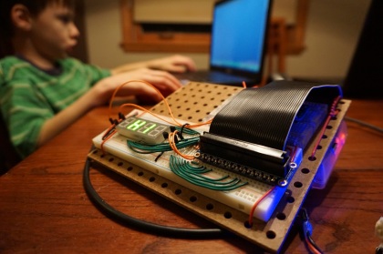
I’m pleased to report that I’ve gotten both the 7-segment score display and LED lights working, controlled by the Teensy 3.1. I hand soldered the MAX7221 onto a board with seven digits for a score up to 9,999,999. It has a jack for power and another for data. It was a bit tedious, but a PCB of this size would have been prohibitively expensive. I breadboarded the MAX6971 constant current LED driver while I waited for the board from OSH Park. It arrived today, and I got it all working. Following Ben Heck’s method, I’m clocking 16-bit packets out on an interrupt with a separate data line for each chip. They each share a clock and latch bus, so only 16 clock cycles are needed to update everything when the timed interrupt fires. I’ve made a bunch of functions, so that when I’m ready to write the game play modes I can easily control the lights and the score. Here’s a brief video showing it in action. -DF
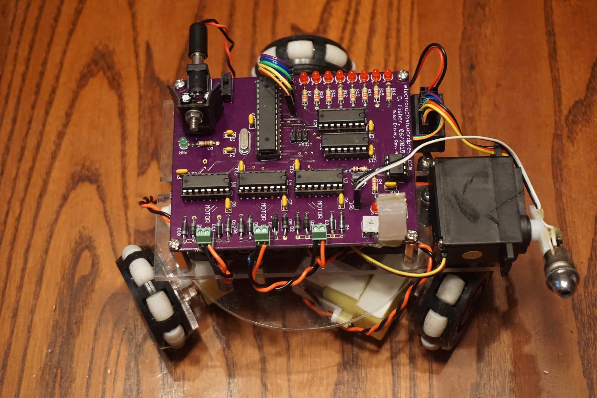
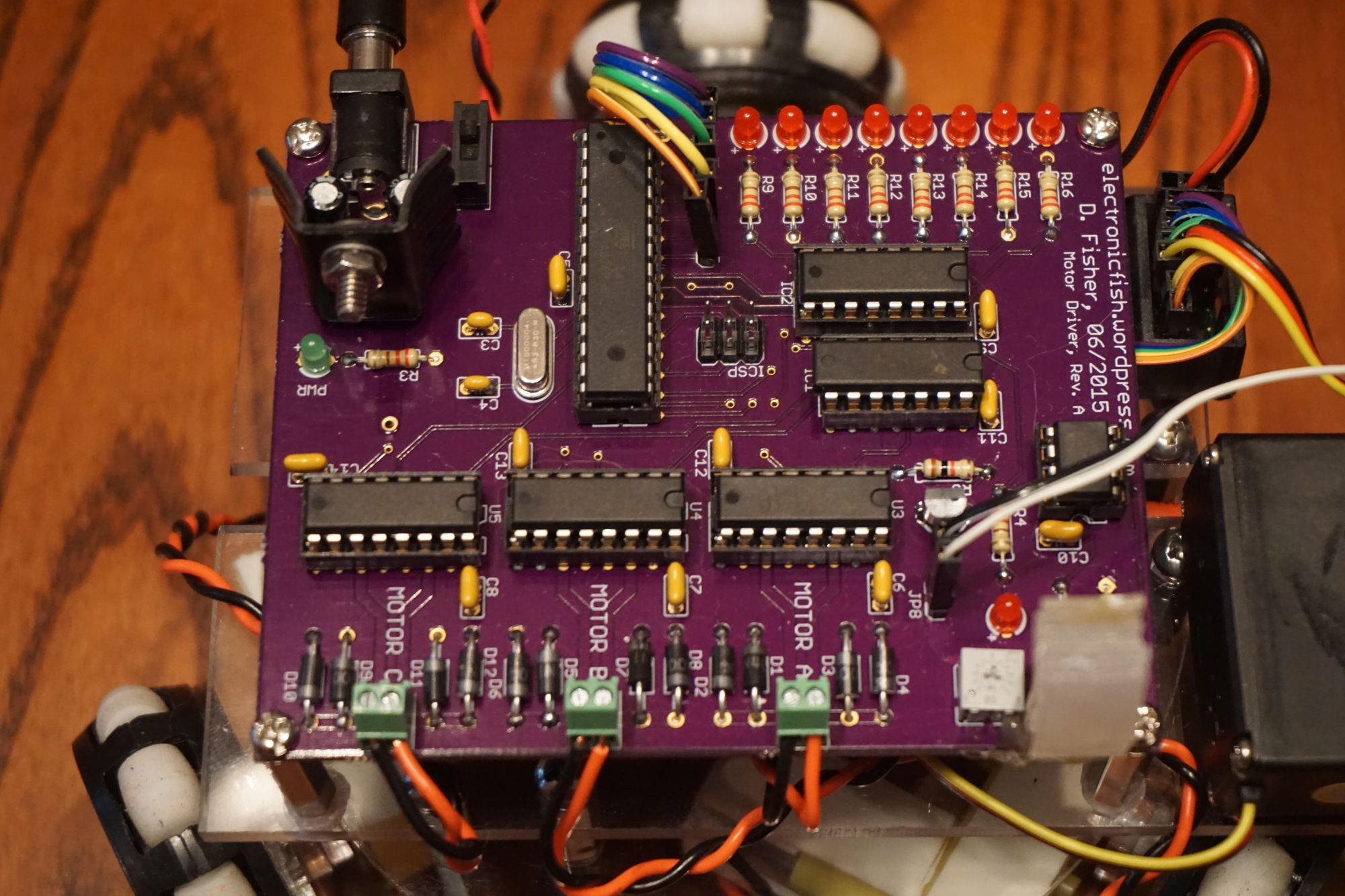
I soldered and tested the PCB from OSH Park a few weeks ago for my omniwheel R/C robot, and I’m quite pleased with the results. I’ll take stuffing parts into a PCB over laborious hand wiring any day! Of course, laying out the PCB was time consuming, being only the second board I’ve designed. With the single board design, I needed to adjust how I built the second robot. For the first one I had three layers above the batteries: main board, support for the laser servo and radio receiver, and the LED/light sensor board. This time, I made the first level above the batteries be a clear acrylic layer to hold the receiver and the laser servo out to the side, and the second (top) level was the PCB. It’s much easier to switch on, plus you get to see the nice purple board from OSH Park.
Here’s a quick intro, including how I made the LED bar into a “laser charge indicator”:
The diffusors are cloudy plastic pieces cut from a VHS cassette case and glued together (thank you, Axman Surplus!). It provides a nice sized target that can be hit from any direction to disable the bot. I made both robots with matching targets to make for a fair fight. I’ve found that the photoresistor sensor works best in evenly lit areas. You can adjust the sensitivity with a 10k trimpot, but if you go from a dark area to a light area the bot can get disabled. Similarly, if you adjust the laser sensor circuit in a brighter area, the bot won’t get disabled when hit in a darker area. Not much of a problem unless you’re fighting right by a window and going in and out of shadows.
Some things to note for a future Revision B:
The comparator circuit to detect a laser hit had the signal LED logically reversed. On the first bot, the LED is normally off/low and goes on/high when a laser hits the photoresistor. This time I was surprise to find the LED normally on. It turns off when a laser hits the sensor, but the logic input to the microcontroller is the same for both. I just need to adjust one or two traces, I think.
The LM7805 linear regulator ran surprisingly hot on the new bot. I haven’t noticed any warming ANYWHERE on the first bot. While all the drive motors take power directly from the batteries, I intended the 7805 to only power the microcontroller and logic circuits. I now see that the laser servo gets its +5V power from the R/C receiver, which in turn is powered by the 7805. It is like this for both robots, but the new one uses a different brand servo that may draw more current. I was able to fit a small heat sink onto the regulator and have had no problems with it. So I need to either source a higher power regulator or slightly adjust the footprints around the regulator to allow for the heat sink.
Most annoyingly, I forgot to provide header pins to power the R/C receiver. Oops! I have it in my hand-wired bot, but it’s on the top board. I just overlooked it when making the schematic and laying out the PCB. I was able to solder on to GND and +5V without much difficultly, but I should definitely fix this for next time.
I would also change all the jacks from straight 0.1″ pitch headers to Molex connectors to avoid accidental unplugging during battle.
With the completion of my laser-tag omnibot project (video of fight robots coming soon!), I’ve been kicking around ideas for my next project. I wanted to get some practice writing some longer embedded code. Being a big fan of The Ben Heck Show, I watched his recent Teensy Pinball Portable build with my 11-year old son who REALLY wanted to build our own. I know pinball machines can get $$pricey$$, but with the smaller size and limited mechanical components it seemed like a good idea. So, I’ve laid out a plan for the electronics and my son has set to work sketching ideas for the playfield and game rules.
I’m basing it closely on Ben Heck’s design, except that the coding for him was a simpler version of his previous pinball builds. I’ll be working from scratch, so it should be a decent challenge. I haven’t used the Teensy 3.1 before, but after checking out some possible Atmel ARM-based chips I decided the ready-to-go Teensy dev board was much more reasonable to start with. It uses an MK20DX256 32-bit ARM Cortex-M4 72 MHz chip, which has much more horsepower compared to the 8-bit ATMEGAs I’ve been using. Here’s a block diagram of the my electronics plans:
We’ll see how it goes. Ben Heck has the shift registers all sharing the CLK and LATCH bus, but each with their own data lines. All the packets are 16-bits, so they all get clocked in or out in one go during an interrupt.
While waiting for the Teensy 3.1, audio adapter, and other components to arrive I laid out a board for the LED driver chip, the MAX6971. I’ll have a bunch of hand soldering to do, but this was another good chance to practice making a PCB that will also save me some work later:
At the beginning of this year I was given the opportunity to participate in the STEM Academy Raspberry Pi Roadtest at element14.com. I was provided the Raspberry Pi Camera Kit (it was the RPi B+ at the time, now it’s 2) and asked to use it with students and then write about it. I ended up not getting down to write all the posts (oops!) but I did complete a project with my son for his winter science project. It was quite the bread-boarded circuit (in fact, I haven’t disassembled it yet)! You can read more about it here at the STEM Academy at element14.com, including a parts list, pictures and code.
In my last post I gave the impression that I did everything myself. Not so! The goals outlined were presented for the class to accomplish. However, since we had limited time (4 weeks) and it wasn’t actually an engineering class but rather an Earth and Space Science class, I assembled the core electronics myself and wrote the framework data logging script. I needed to know that we at least had some chance of recovering our data and equipment. The 16 student class self-selected into 4 groups:
hardware/software – assemble and test electronics, edit data logging script
payload container – design and build the payload container, assist in installing electronics
launch logistics – research launch requirements, source and price helium, send at least some team members to the actual launch
project/data representation – document the project with photos and online presentation (website or other)
It this way, the students all had some share in the project without every student having to wire or program electronics. I will adjust this arrangement for next year, as some teams ended up with less work to do than others. I’d like to have each student team design and construct some type of experiment to fly underneath the main electronics payload that I provide. That way there is a definite need for each team to work toward the end goal the entire time. As it was, teams had uneven responsibilities. Attending the launch was optional, as it had to occur on a weekend and students would have to provide their own transportation for what was likely to be a day-long event.
Launch equipment
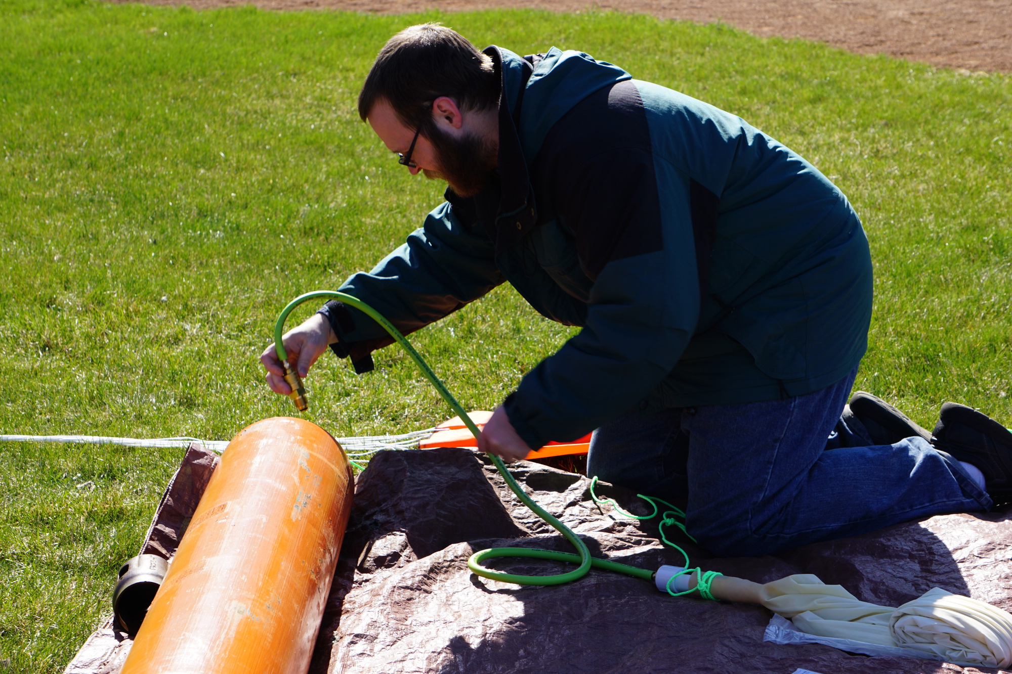
I selected a 600g weather balloon from High Altitude Science, along with their regulated balloon inflator and 1.0 m parachute. I would recommend all of these products for future flights. The trickiest bit was purchasing the right amount of helium. The volume required depends upon how heavy your payload is. This was my first flight, so I was nervous about handling high pressure gas and potentially losing some due to leakage. Practically speaking, it’s better to have too much than too little. So in the end I opted for the K-size cylinder (which contains 217 cubic feet) from the local Toll Gas. Any welding or industrial gas supply store will have the same available, but it was costly – about $180! This was the one area that cost significantly more than I first estimated.
Launch logistics
I envisioned launching the balloon from school at first, but that was quickly squelched. The Minneapolis-St. Paul International Airport constitutes a Class B airspace, which makes a wide area around it unsuitable for balloon launches. Furthermore, prevailing weather patterns would make a launch west of the Twin Cities likely to drift into densely populated areas. We used predict.habhub.org to predict possible flight plans in the days leading up to launch and select a park to launch from. The prediction was spot on, and I again recommend this service.
Despite my nervousness about handling the large helium tank, it fit into my minivan without any problems and it could be carried by two strong lads from the van to the launch field. In fact, I even fit it into my small Toyota Echo to return it to the gas vendor (from the trunk through to the opened back seat).
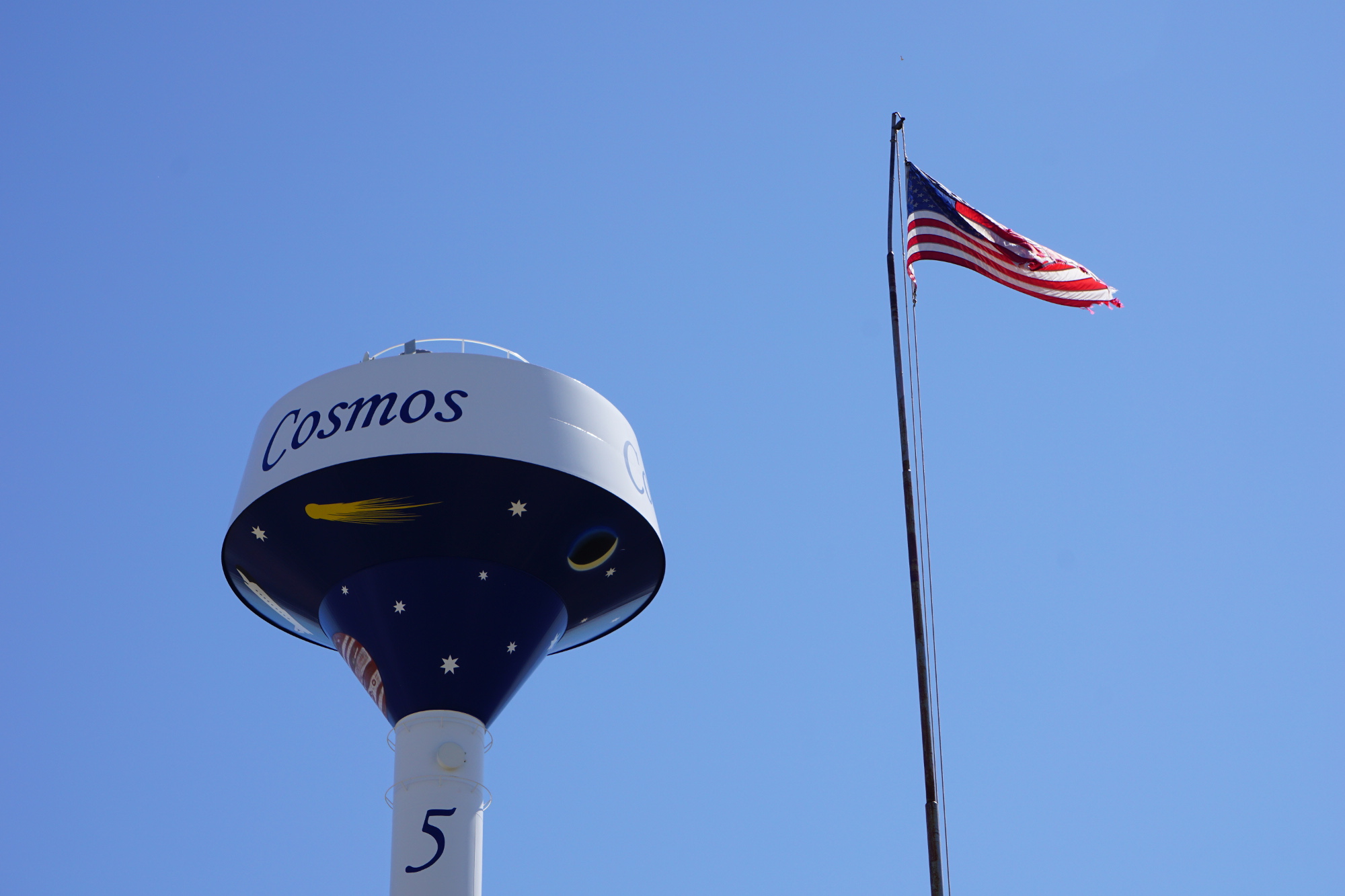
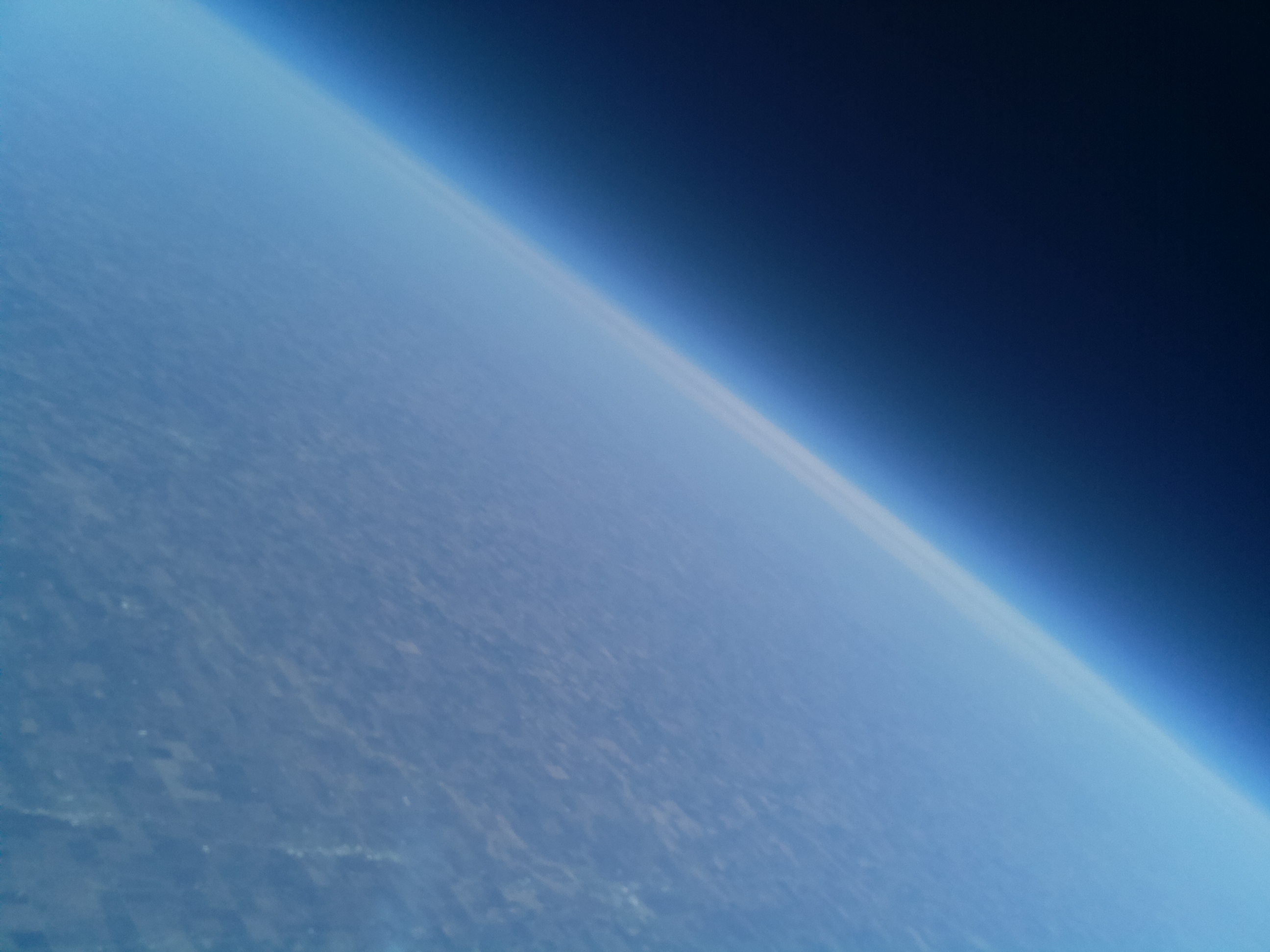
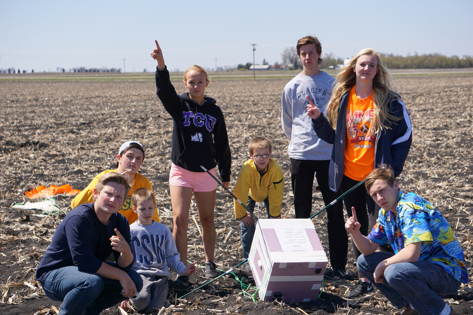
The free app provided by SPOT sent great tracking data to use every 5 minutes via my smart phone. Following the 10:15 AM launch, we relaxed in the beautiful morning sunshine watching the balloon tracks get further and further south. Then we drove about 15 miles south to a park near the predicted landing zone. Coincidentally, this park was in the town of Cosmos, MN where streets are named things like Milky Way drive! It was a good time. When the SPOT Trace sent its “stop” signal we followed the map straight to the field where it landed! I was quite relieved to see it safe and sound. From a nearby driveway I setup the wifi network and backed up all photos and data from the Raspberry Pi. We got some just spectacular shots on a crystal clear morning.
Flight summary
Date: Sunday, April 26, 2015
Release time: 10:16 AM (CDT)
Balloon burst time: 11:38 AM (CDT)
Balloon touchdown: 12:12 AM (CDT)
Distance traveled: 20.2 miles, mostly south
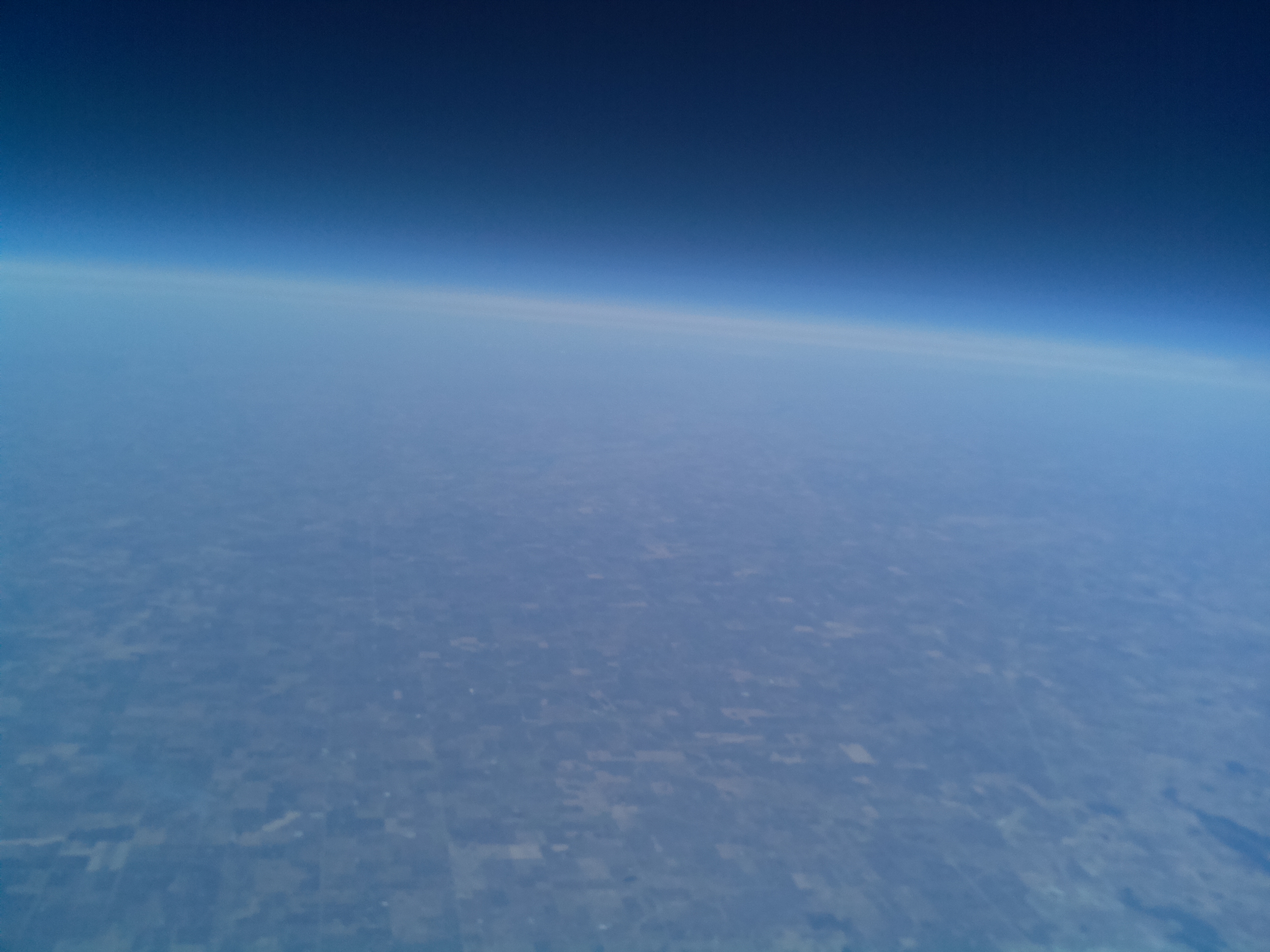
Maximum recorded altitude at balloon burst: 27469.5 meters (90,100 feet) above sea level
Maximum speed during descent: 51.5 m/s (115 mph)! This was achieved in the very thin atmosphere less than a minute after balloon burst.
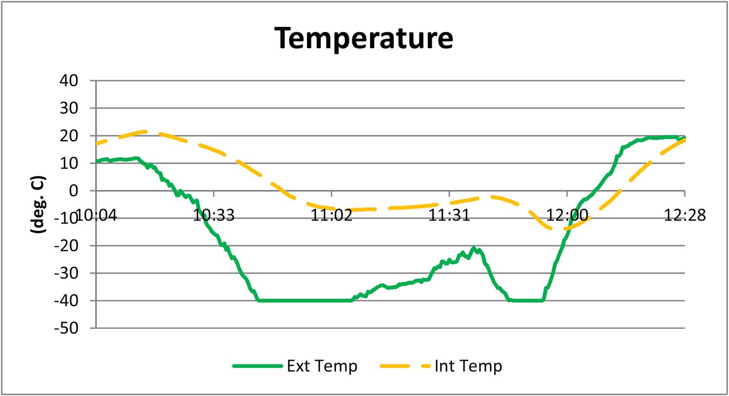
Data
Notice that the interior temperature did stay significantly above the exterior
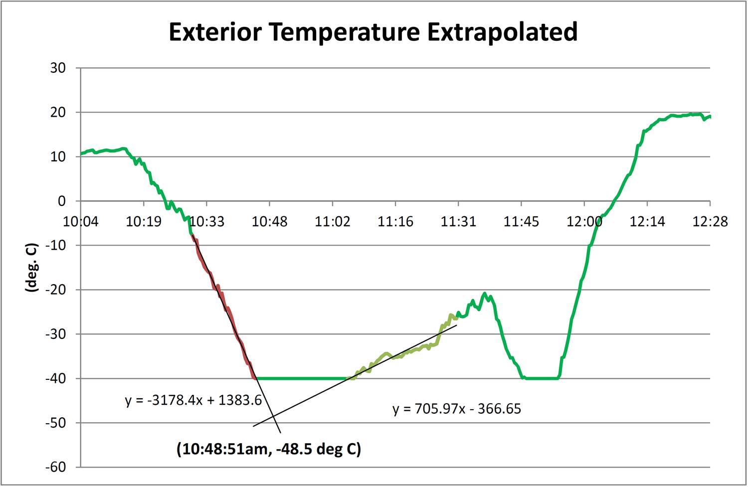
This is my attempt to estimate the minimum temperature encountered
Thoughts for next time…
As I mentioned above, I plan to organize the class differently next year with each team preparing its own small scientific payload. I’d like to upgrade the radio communications to provide live data packets. The SPOT did indeed cut out at 60,000 ft, leaving a blind period in the middle of flight when we just had to wait and hope for another signal. I’ll either try to rig my own transmit/receive setup, or perhaps transmit APRS packets that can be viewed via a webpage tracker. I’m planning to fly a larger balloon (1200g) which should carry a heavier payload to a higher altitude. I’d like to find a digital sensor than doesn’t bottom out at -40 degrees C. In the end, the project was successful and definitely worthwhile! -DF
The most logistically challenging project I’ve tackled this year was coordinating a high altitude balloon launch into the stratosphere with my senior science class at the high school where I teach. I had toyed with the idea during the 2013-14 school year, but wasn’t quite ready for it. This year, I was thinking about how to stave off “senioritis” and had funds available in my budget that I could re-purpose. Instead of trying to engage my class in a discussion about climate change (current event, politics, debate!), I opted for the high altitude balloon (HAB) project and we dove in after spring break.
Project goals: To design, create, and launch a HAB that:
broadcasts its GPS coordinates in order to be retrieved
logs GPS and sensor data including: latitude, longitude, altitude, pressure, temperature, humidity
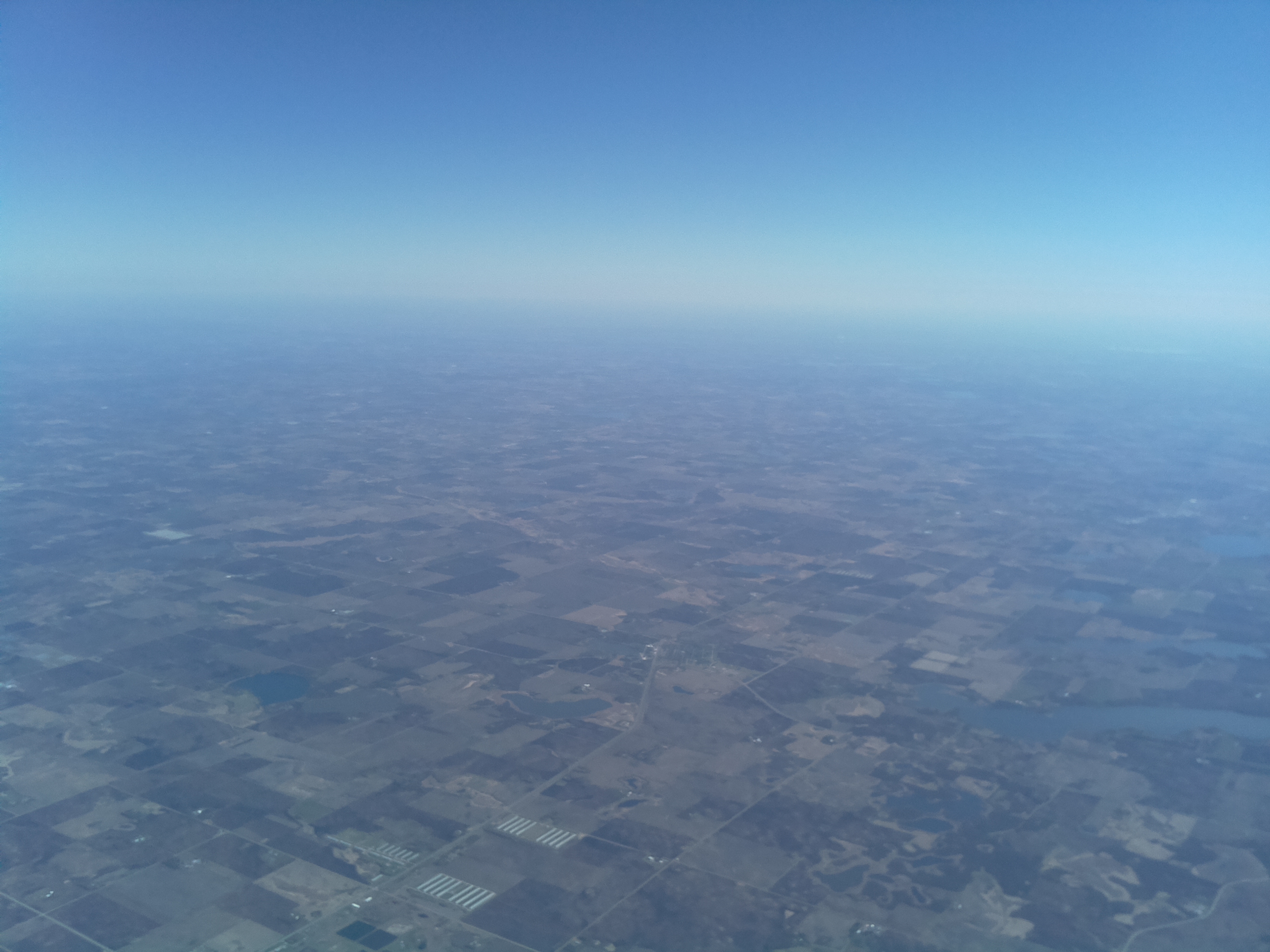
captures still images at regular intervals during both ascent and descent
Because I had experience with a lot of these functions in my Raspberry Pi weather station, I decided to make that the core of the flight electronics. I used the same sensors I had used previously (the DHT22 for exterior temp. and humidity, and the BMP180 for interior temp. and pressure). The challenges I needed to solve were: power at low temperature, auto capturing images using the Raspberry Pi camera module, GPS location, and radio communications.
Power
Following other HAB launchers’ advice, I opted on using lithium batteries that could perform well at low temperature (perhaps approaching an exterior temperature of -55 degrees C). I put together a pack of 8 Energizer Ulimate Lithium AA batteries that fed a nominal 12V into a UBEC buck converter to provide a regulated 5V to the RPi. On a separate 9V supply (3 lithium 9V batteries in parallel), I had a resistive heater circuit to help keep the inside of the payload a bit warmer. The main AA pack ended up being more than enough for the 2 hour flight. I tested the heater circuit at home with regular alkaline 9V batteries. The 3 ohm power resistor got REALLY hot at the start, then gradually reduced to warm at about 1.5 to 2 hrs later. I think the on-board heater served its purpose during flight (see interior temperatures below), but I never flat out tested the lithium batteries in the heater since they were expensive and I wanted to save them for the flight. If anything, for next time I’d like to look for a lighter power solution, but this combo worked well.
Also, I flew the lower power Raspberry Pi A+ to help reduce power requirements. During development, we had a cheap 4-jack USB hub plugged in to allow more places for keyboard and mouse peripherals to connect. During the flight itself, I kept only a USB wifi dongle plugged in to the single USB port on the RPi. This allowed me to SSH into the Pi before launch to verify that everything was ready to go. I configured an old wifi router to create a wifi network for this purpose (it plugged into a 110VAC inverter powered from my van’s 12V lighter on launch day).
Camera
The Raspberry Pi camera module is supported by an easy to use Python library, Picamera. Since I hadn’t used it before, I practiced capturing time lapse images of the construction at my school. The script captured images, time stamped them, saved them, and uploaded them to my Google Drive account. Here’s the resulting video I cut together:
Of course, for the HAB flight, only saving each image to the Pi’s SD card was required.
GPS location
GPS presented many options to choose from. The chief requirement was that the antenna not shut down at too low of an altitude (many do as a safety feature). At first, I researched using one GPS antenna for both logging and tracking using APRS. However, without a ham radio license, this solution was both too time consuming and too cost prohibitive. I decided to do GPS logging separate from GPS tracking. I purchased the Ultimate GPS Hat from Adafruit for logging along with an external active antenna and adapter cable. This would give latitude, longitude, and altitude. The GPS module on the hat also has a real time clock with battery backup so that I could get an accurate time even if the RPi isn’t connected to the internet at boot (the RPi has no real time clock of its own).
Using the prototyping space conveniently included on the GPS hat, I soldered header pins for the temperature sensor and for the little buzzer we included to help in finding the payload. I also included an indicator LED to help blink when the Pi had recorded a data point.
For next year, I would like to consolidate the logger together with the tracker.
Radio communication
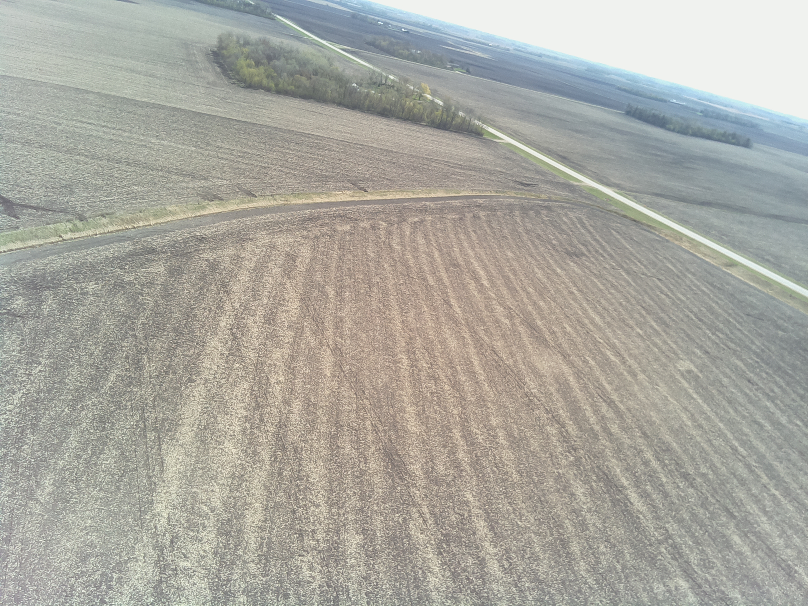
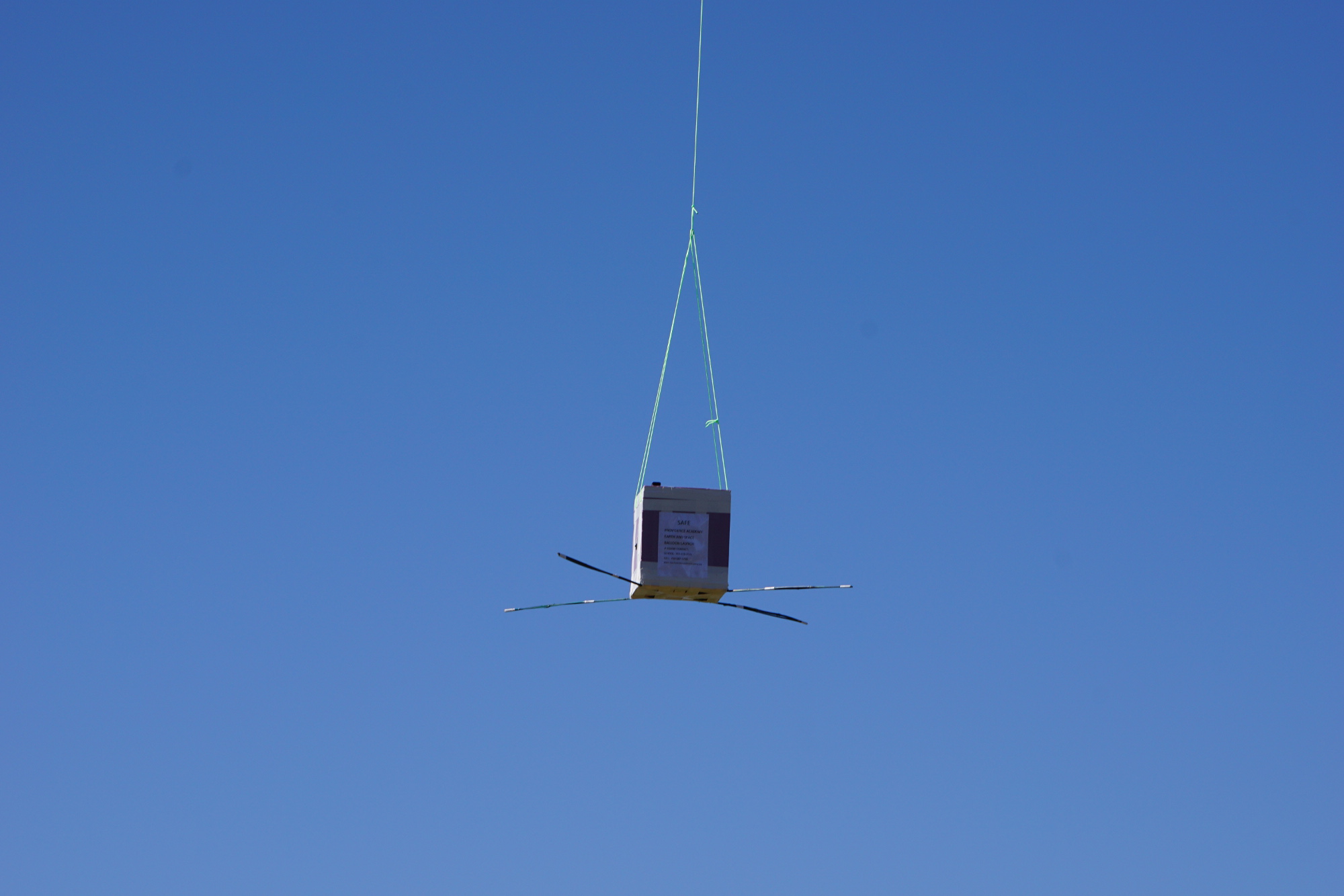
Radio communication and tracking is an area with even MORE options than GPS location! Since I don’t have an amateur radio licence, and setting up other 2-way communication with the balloon computer would require even more hardware on the ground ($$ read too expensive $$) I went the the simple SPOT Trace gps tracker. It is an all-in-one GPS receiver and location transmitter. It communicates its location to a satellite as well, so it can’t go “out of range”. It sends its latitude/longitude every 5 minutes (no altitude) to its proprietary website where you can view it through a web browser or a mobile app. It does require a year “subscription” to use, which is less than ideal for our once-a-year project ($100 for the device, and another $100 for the service). The one thing it needs is a clear view up at the sky. I was most worried that the payload would land upside down and we’d lose the payload upon landing. So my students attached thin bamboo sticks extending from the corner to widen the base and hopefully reduce the chance of it flipping. It didn’t keep the payload box completely upright, but neither was it completely upside down. We got a successful STOP message from the SPOT which led us straight to the landing spot it an unplanted cornfield.
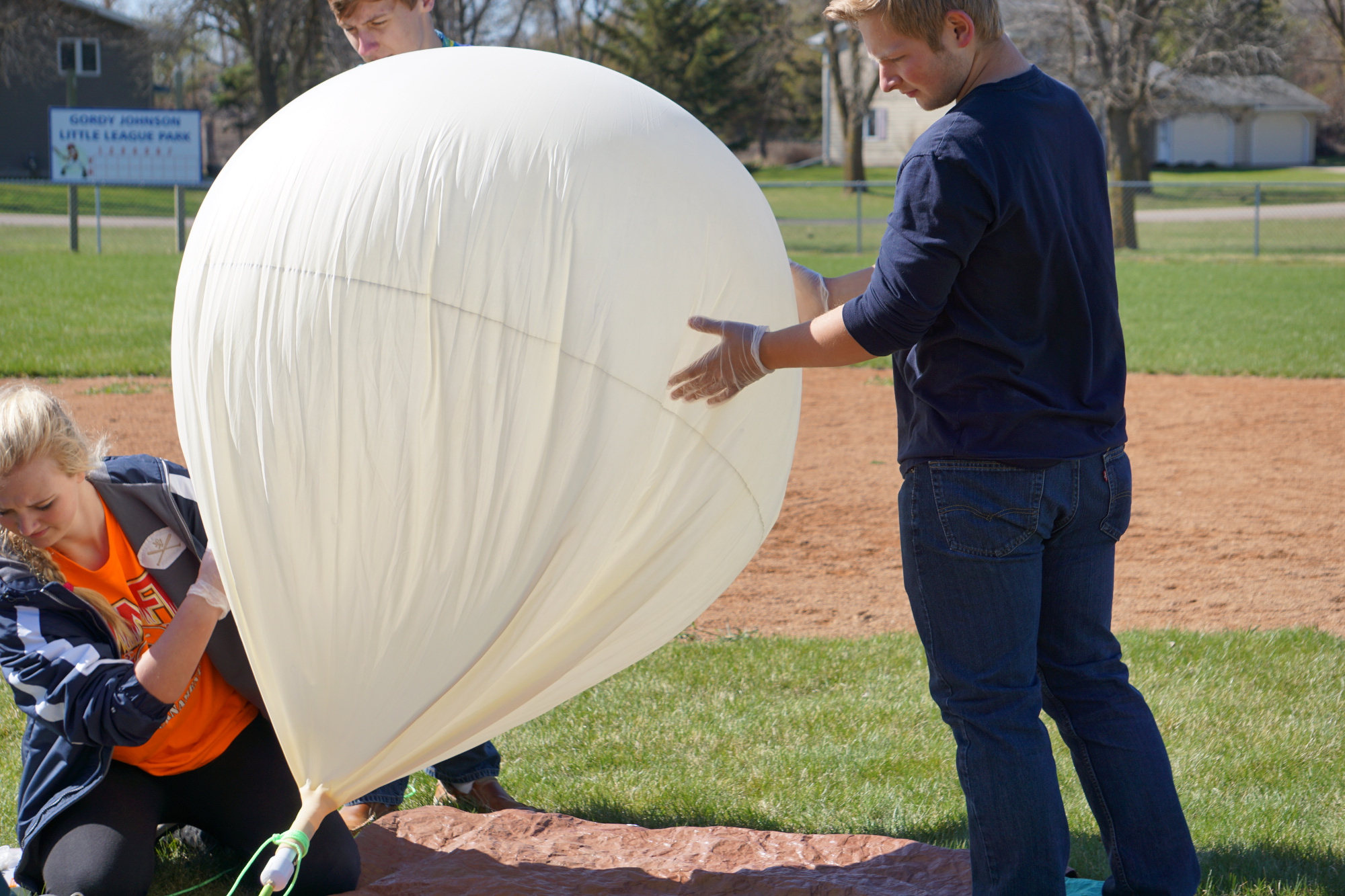
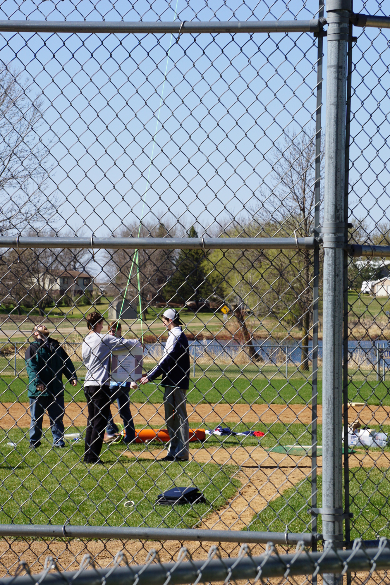
I’ll end with a few more images of the payload from launch day. Next time I’ll share flight images as well as the data we recovered. In the end, it was a successful flight and recovery! -DF
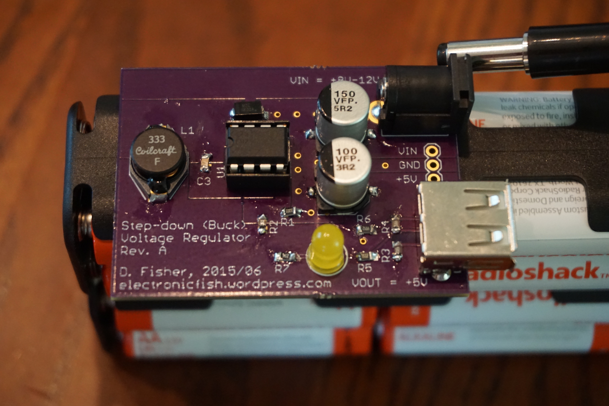
I received my PCBs from OSH Park late last week and got to work soldering components. It was my first time using surface mount components by hand so I was cautious, especially with the tiny 0805 resistors and capacitor. I would have chosen something bigger, but 0805 was by far the easiest size to find on Digi-Key. It went fine. I went one component at a time so that I didn’t end up with a pile of tiny resistors on the bench that were too small to identify! Tweezers and patience paid off and everything found its place.
The first time I powered it up, the converter output +5 V (yay!), but the power LED didn’t light up. It turned out that the silk screen for the 5mm LED was reversed, so that I soldered the LED in backwards. It was a bit of a pain to de-solder since I didn’t include thermal separation from the top power plane and bottom ground plane. Once it was the right way around, no more problems.
I tested the output voltage both with and without load and it held steady at +5V. Both Apple and Android devices charged without problem, including my iPad 2. Using fresh alkaline batteries, I charged my iPad from 5% to 100%. With the same batteries I topped off the last 10% of my wife’s phone. Then I took her iPad mini from about 75% to 85%, all on the same batteries! I was curious as to how long they would go, so I (informally) monitored Vin and Vout as the batteries drained. Vout held steady at +5 V even as Vin dropped past +6.5 V. Finally, Vout began to drop. Strangely, the iPad kept saying it was charging even as Vout got down to +4.2 V, but the percent charge stopped increasing. I wanted to see how much current was being drawn, but I didn’t take the time to insert the multimeter in between the USB jack and the board. It seemed to charge the iPad handily, and the buck IC only got a bit warm so I’m guessing the current was up there around 1 A. However, I would like to test it more in the future.
Things to improve for revision B:
Increase the annular rings around the IC through-holes. I used the auto-sized rings and should have increased them myself.
My first longer term project, begun over a year ago, was my Raspberry Pi weather station. It began as an Arduino-based weather station. The goal was to measure various weather variables using sensors, store the data, and then send it somewhere. I teach a high school course called Earth and Space Science, which includes a unit on the atmosphere and weather. Wouldn’t it be great to have a class weather station to use for data collection? Since I was learning about Arduino programming at the time, I spent a considerable about of time building a custom hand-soldered shield for the UNO and writing code for it. But in the end, the limited flash memory and ram of the Arduino (ATMEGA328P), together with connectivity issues, made the end result unreliable. I was grabbing several libraries to read the sensors, as well as log to an SD card, AS WELL AS sending http get requests over wifi with a CC3000 shield. It was too much, and it didn’t work for more than a few hours without freezing up. I set it aside for some months.
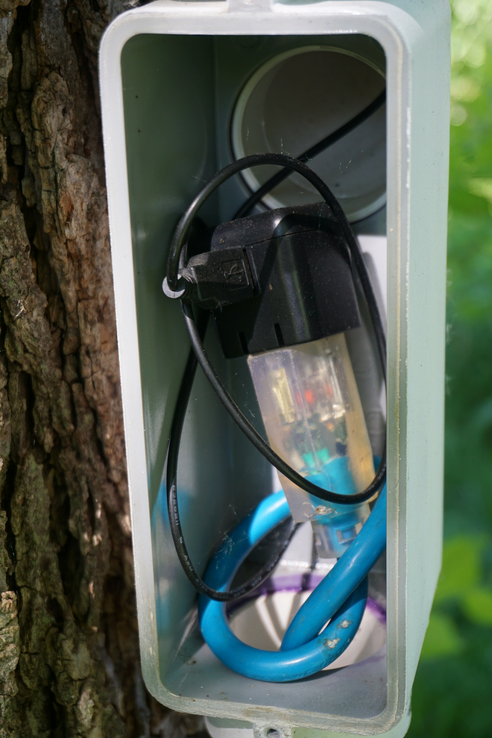
The project was resurrected when I took up learning about the Raspberry Pi and coding with Python. The limitations of the simple 8-bit Arduino microcontroller are handled nicely by the more capable Pi system-on-a-chip. With a simple wifi dongle, I could connect to my home network without problems. I soldered a small bit of perf-board to plug into the Raspberry Pi Model B GPIO pins. The pressure sensor is wired directly to board, which is inside the enclosure. Since the air pressure would equalize between the inside and outside of the stations, I didn’t need to get the pressure sensor outside. The temperature/humidity sensor and light (lux) sensors are plugged into header pins on the perf-board so they can be both strung outside and unplugged as needed.
Here is my working code (with my own station id and password removed). It is set to run automatically at boot with an entry in the Pi’s crontab. (I’ll let you google how to autorun scripts in Linux. Have fun!)
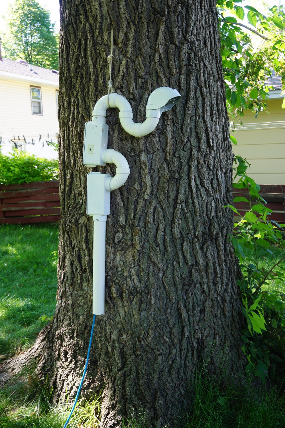
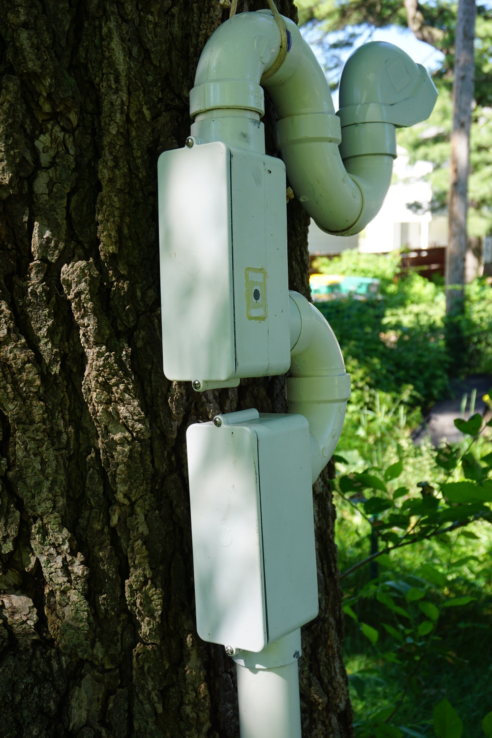
Enclosure:
I used PVC conduit boxes and pipes from the hardware store to weatherproof my station. The power adapter is in the lower box to keep extra heat away from the board and sensors. The exterior temperature is taken at the end of the bending pipe and hood, protected from rain. The Raspberry Pi core is in the top box. The bending pipe is to prevent any blowing rain or snow from getting to the Pi. I even drilled holes in bottom of the “U” section to allow any collected moisture to drip out. After over a year outside in harsh Minnesota weather, I have had no problems with moisture.
I have just two minor problems with the design as it currently stands. Every once in a long while the Pi freeze and stop transmitting. I have to unplug the station to get it to reboot (SSH won’t let me in). This is only once every 1-2 months. Also, my station does not have a proper radiation shield, making it sensitive to direct sunlight. I have placed it in the shade of a large tree, but I still see spikes in my temperature data when sunlight hits it. -DF